Pneumatic Symbols Chart
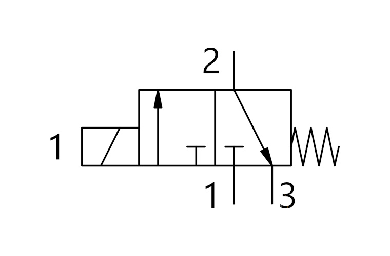
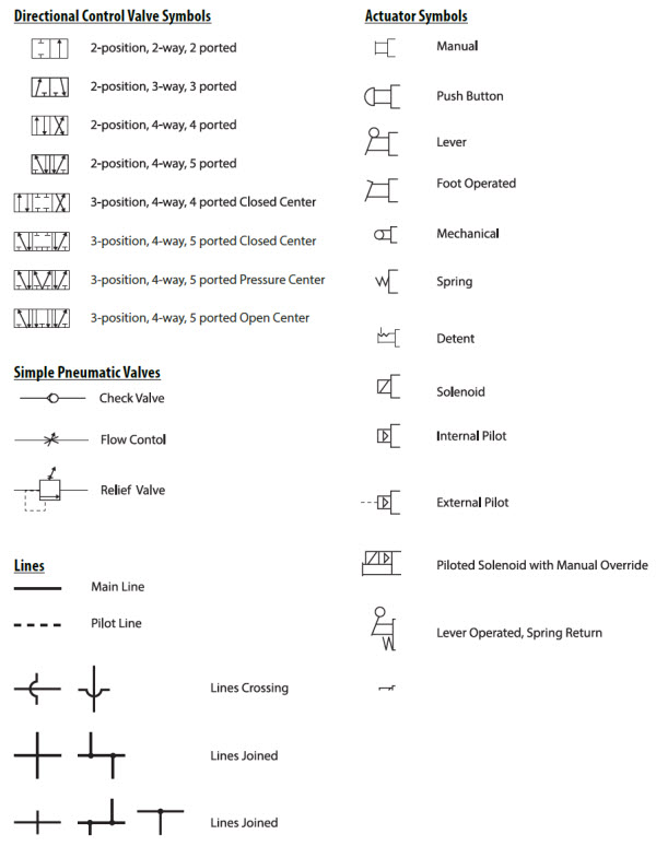
Pneumatic Symbols Chart - Web pneumatic circuit symbols representing these valves provide detailed information about the valve they represent. Web combined vertical lift and horizontal motion. Web practicalguide pneumatics pneumatics t contents 2 cha 2 pneuma circ s e cha 6 pneumatic t hose cha 4 pneuma actuat (a c asics cha 9 electr pneuma syst action cha 12 pneuma actuat vs electromechanical cha 3 u pneuma a preparation cha 8 ar pneumatic components compatibl9 cha 11 ener e˜cien pneuma systems cha 5 valv or pneuma cylinders cha 10 Scan through and easily download the one you need. Use simplified pneumatic symbols for faster, easier, and more creative pneumatic circuit design. Web here is a complete chart of the basic valves, actuators, combinations and the auxiliary components used in pneumatic logic control circuitry. Copyright 1985 clippard instrument laboratory. Here is a brief breakdown of how to read a symbol. Fm(n) = fv2 + fh2. How do i select a pneumatic symbol? Use simplified pneumatic symbols for faster, easier, and more creative pneumatic circuit design. Calculate the force on a 10kg mass with a dry surface, a change in acceleration of 3m/sec2, and a change in travel acceleration of 2m/sec2. Web pneumatic circuit symbols representing these valves provide detailed information about the valve they represent. Copyright 1985 clippard instrument laboratory. Directional air. Symbols show the methods of actuation, the number of positions, the flow paths and the number of ports. Web all the symbols you need to design your pneumatic circuit in.dxf format. Web pneumatic circuit symbols representing these valves provide detailed information about the valve they represent. Web the chart above shows a good representation of common symbols and more is. Use simplified pneumatic symbols for faster, easier, and more creative pneumatic circuit design. Web pneumatic circuit symbols representing these valves provide detailed information about the valve they represent. Web practicalguide pneumatics pneumatics t contents 2 cha 2 pneuma circ s e cha 6 pneumatic t hose cha 4 pneuma actuat (a c asics cha 9 electr pneuma syst action cha. Calculate the force on a 10kg mass with a dry surface, a change in acceleration of 3m/sec2, and a change in travel acceleration of 2m/sec2. Scan through and easily download the one you need. Web here is a complete chart of the basic valves, actuators, combinations and the auxiliary components used in pneumatic logic control circuitry. Web pneumatic circuit symbols. Symbols show the methods of actuation, the number of positions, the flow paths and the number of ports. How do i select a pneumatic symbol? Web pneumatic circuit symbols representing these valves provide detailed information about the valve they represent. Fm(n) = fv2 + fh2. Scan through and easily download the one you need. Calculate the force on a 10kg mass with a dry surface, a change in acceleration of 3m/sec2, and a change in travel acceleration of 2m/sec2. Fm(n) = [(10kg x 2m/sec2) x 4]2 + [10kg x (9.81m/sec2 + 3m/sec2) x 2]2 fm(n) = (80kgm/sec2)2 + [256kgm/sec2]2. Directional air control valves are the building blocks of. Web practicalguide pneumatics pneumatics t contents. Web here is a complete chart of the basic valves, actuators, combinations and the auxiliary components used in pneumatic logic control circuitry. Scan through and easily download the one you need. Fm(n) = [(10kg x 2m/sec2) x 4]2 + [10kg x (9.81m/sec2 + 3m/sec2) x 2]2 fm(n) = (80kgm/sec2)2 + [256kgm/sec2]2. Web practicalguide pneumatics pneumatics t contents 2 cha 2. Web all the symbols you need to design your pneumatic circuit in.dxf format. Copyright 1985 clippard instrument laboratory. Use simplified pneumatic symbols for faster, easier, and more creative pneumatic circuit design. All the symbols you need to design your pneumatic circuit in.dxf format. Directional air control valves are the building blocks of. Scan through and easily download the one you need. Web the chart above shows a good representation of common symbols and more is outlined below. Web all the symbols you need to design your pneumatic circuit in.dxf format. Use simplified pneumatic symbols for faster, easier, and more creative pneumatic circuit design. Copyright 1985 clippard instrument laboratory. Web practicalguide pneumatics pneumatics t contents 2 cha 2 pneuma circ s e cha 6 pneumatic t hose cha 4 pneuma actuat (a c asics cha 9 electr pneuma syst action cha 12 pneuma actuat vs electromechanical cha 3 u pneuma a preparation cha 8 ar pneumatic components compatibl9 cha 11 ener e˜cien pneuma systems cha 5 valv or pneuma. Directional air control valves are the building blocks of. How do i select a pneumatic symbol? Fm(n) = fv2 + fh2. Web here is a complete chart of the basic valves, actuators, combinations and the auxiliary components used in pneumatic logic control circuitry. Web pneumatic circuit symbols representing these valves provide detailed information about the valve they represent. Web all the symbols you need to design your pneumatic circuit in.dxf format. Web combined vertical lift and horizontal motion. Use simplified pneumatic symbols for faster, easier, and more creative pneumatic circuit design. Copyright 1985 clippard instrument laboratory. Calculate the force on a 10kg mass with a dry surface, a change in acceleration of 3m/sec2, and a change in travel acceleration of 2m/sec2. Fm(n) = [(10kg x 2m/sec2) x 4]2 + [10kg x (9.81m/sec2 + 3m/sec2) x 2]2 fm(n) = (80kgm/sec2)2 + [256kgm/sec2]2. Scan through and easily download the one you need. Symbols show the methods of actuation, the number of positions, the flow paths and the number of ports.
Pneumatic Symbols Ppt bmpvirtual

Actuator Pneumatic Symbols AutoCAD Free CAD Block Symbols And CAD
Reading Pneumatic Schematic Symbols

Pneumatic Symbols Chart With Meanings

Pneumatic Symbols Chart With Meanings
Pneumatic Symbols PDF

Pneumatic Circuit Symbols Explained Library.AutomationDirect

Pneumatic Symbols Ppt bmpvirtual

Schematic Hydraulic And Pneumatic Symbols Hydraulic systems

Pneumatic Diagram Symbols Light Switch Wiring Diagram
Web The Chart Above Shows A Good Representation Of Common Symbols And More Is Outlined Below.
All The Symbols You Need To Design Your Pneumatic Circuit In.dxf Format.
Web Practicalguide Pneumatics Pneumatics T Contents 2 Cha 2 Pneuma Circ S E Cha 6 Pneumatic T Hose Cha 4 Pneuma Actuat (A C Asics Cha 9 Electr Pneuma Syst Action Cha 12 Pneuma Actuat Vs Electromechanical Cha 3 U Pneuma A Preparation Cha 8 Ar Pneumatic Components Compatibl9 Cha 11 Ener E˜cien Pneuma Systems Cha 5 Valv Or Pneuma Cylinders Cha 10
Here Is A Brief Breakdown Of How To Read A Symbol.
Related Post:

