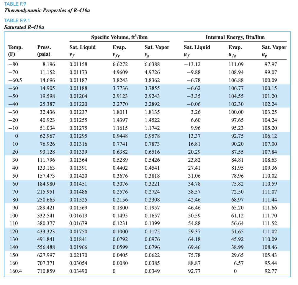
R410A Charging Chart
R410A Charging Chart - Measure air temperature to outdoor coil. Overview of 410a refrigerant properties and benefits. Pressure at suction service port (psig) instructions: Monitor the subcooling and superheat. Calculate the target subcooling and superheat. What is the pressure of r410a at 72 degrees fahrenheit? Web the r410a pt chart can be used to answer questions like: Ensure the thermometer makes adequate contact and is. The photo shows both sides of the tool. What are normal operating pressures for 410a? Web here are the steps to properly charge a 410a ac system: Furthermore, r410a is an hfc and is commonly used in residential and light commercial hvac equipment for air conditioners and heat pump systems. Monitor the subcooling and superheat. General wire spring/general pipe cleaners. For best results, temporarily install a thermometer on the suction line near the compressor. Overview of 410a refrigerant properties and benefits. Web 14 seer r410a ac charge chart 5 ton outdoor ambient temperature(℉) liquid pressure at small service valve(psig) 55 60 65 70 75 80 85 90 95 100 105 110 115 165 161 157 153 149 145 141 137 133 129 125 121 117 113 109 105 cooling mode outdoor ambient temperature(℉) liquid. Do not use mercury or dial type thermometers. Service manual (381 pages) , installation manual (177 pages) , technical data manual (37 pages) 1. 6) if more than 5 degrees under, remove charge to increase line temperature. General wire spring/general pipe cleaners. Run system at least 10 minutes to allow pressure to stabilize. General wire spring/general pipe cleaners. For best results, temporarily install a thermometer on the suction line near the compressor. Web temp (°f) pressure temp (°c) temp (°f) pressure temp (°c) temp (°f) temp (°c) pressure temp (°f) pressure temp (°c) Pressure at suction service port (psig) instructions: Are you overcharging cooling systems? Web the r410a pt chart can be used to answer questions like: Web 14 seer r410a ac charge chart 5 ton outdoor ambient temperature(℉) liquid pressure at small service valve(psig) 55 60 65 70 75 80 85 90 95 100 105 110 115 165 161 157 153 149 145 141 137 133 129 125 121 117 113 109 105 cooling. Overview of 410a refrigerant properties and benefits. Place an x on the appropriate chart where the suction and liquid pressures cross. General wire spring/general pipe cleaners. Use a digital thermometer for all temperature measurements. Measure air temperature to outdoor coil. 5) if more than 5 degrees over, add charge to decrease line temperature. Web this is a very useful tool that takes the guess work out of charging cooling systems. Measure the system’s pressures and temperatures. 6) if more than 5 degrees under, remove charge to increase line temperature. Connect pressure guages to suction and liquid ports at outdoor unit. Design subcooling @ 95 ̊f ambient = 10 ̊f (at service valve). Design subcooling @ 47 ̊f ambient = 25 ̊f (at service valve) add additional amount as shown in table below. Web 14 seer r410a ac charge chart 5 ton outdoor ambient temperature(℉) liquid pressure at small service valve(psig) 55 60 65 70 75 80 85 90 95 100. 6) if more than 5 degrees under, remove charge to increase line temperature. 5) if more than 5 degrees over, add charge to decrease line temperature. Measure air temperature to outdoor coil. Web here are the steps to properly charge a 410a ac system: Calculate the target subcooling and superheat. Run system at least 10 minutes to allow pressure to stabilize. General wire spring/general pipe cleaners. Pressure at suction service port (psig) instructions: Heating basic system charge with 0 feet of tubing = 372 oz. Use a digital thermometer for all temperature measurements. Do not use mercury or dial type thermometers. It is important to know the range of these pressures in order to understand why and how charging and recovery are performed. Web the r410a pt chart can be used to answer questions like: Connect pressure guages to suction and liquid ports at outdoor unit. Furthermore, r410a is an hfc and is commonly used in residential and light commercial hvac equipment for air conditioners and heat pump systems. Overview of 410a refrigerant properties and benefits. Calculate the target subcooling and superheat. Monitor the subcooling and superheat. Measure air temperature to outdoor coil. Web 4) actual line temperature should = chart temperature above. Web here are the steps to properly charge a 410a ac system: What is the pressure of r410a at 72 degrees fahrenheit? 6) if more than 5 degrees under, remove charge to increase line temperature. Service manual (381 pages) , installation manual (177 pages) , technical data manual (37 pages) 1. Design subcooling @ 47 ̊f ambient = 25 ̊f (at service valve) add additional amount as shown in table below. Measure wet bulb temperature with a sling psychrometer or a temperature and humidity thermistor.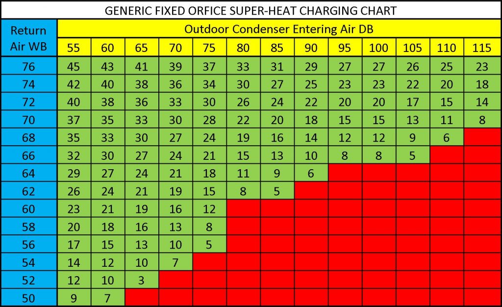
R410a Charging Chart amulette
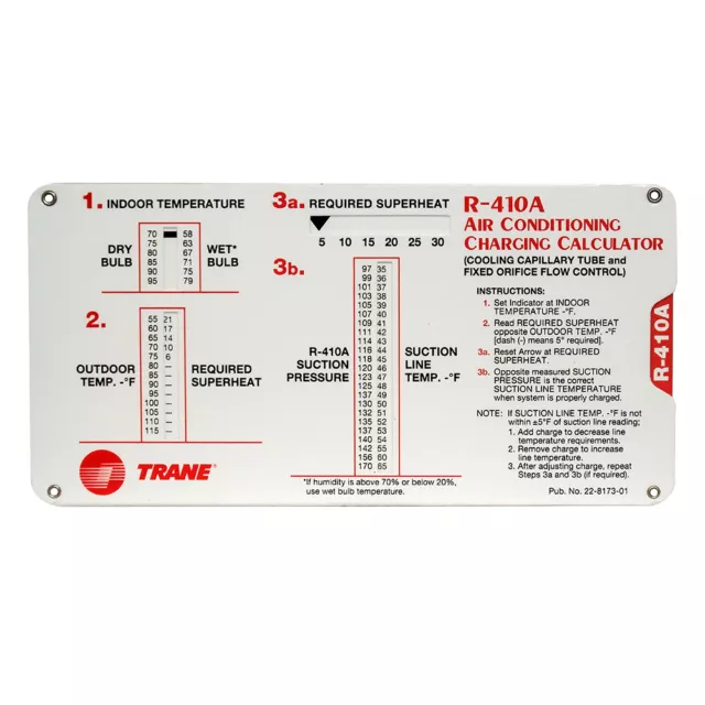
TRANE R 410A R410A Superheat Subcooling HVAC Calculator Charging Chart

Using the Total Superheat Charging Method for HVAC Units!
Printable Refrigerant Pt Chart
R410a system
R410a system
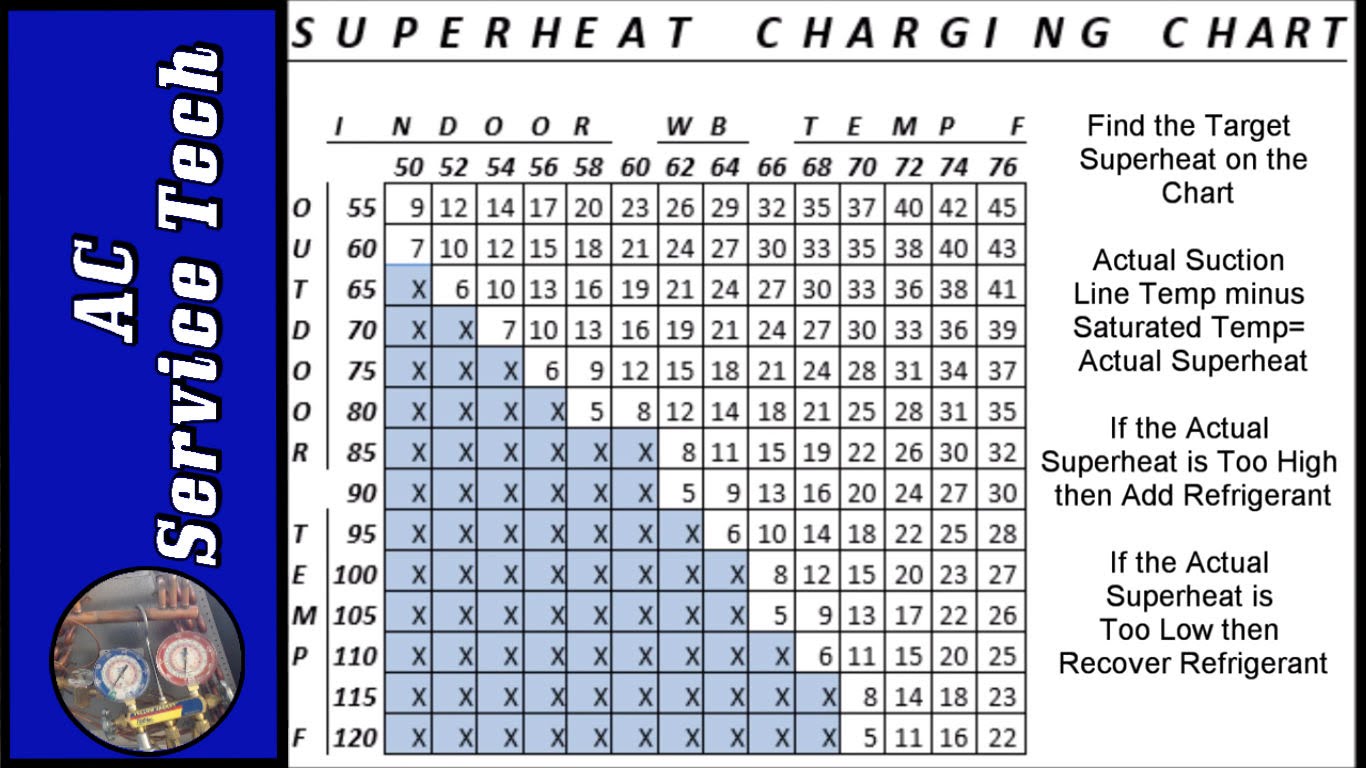
R410a Charging Chart amulette

R410a Charging Chart amulette
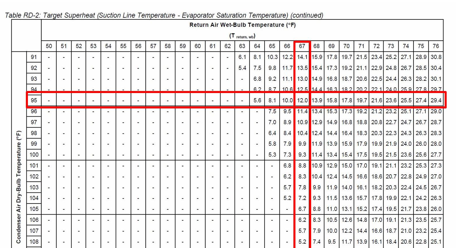
R410a Charging Chart amulette
R 410a Chart
Web System Charge Chart (Cooling) 500.
Web Temp (°F) Pressure Temp (°C) Temp (°F) Pressure Temp (°C) Temp (°F) Temp (°C) Pressure Temp (°F) Pressure Temp (°C)
5) If More Than 5 Degrees Over, Add Charge To Decrease Line Temperature.
Ensure The Thermometer Makes Adequate Contact And Is.
Related Post:
