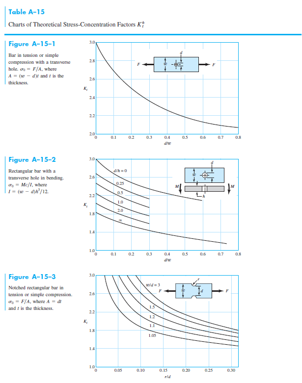
Stress Concentration Factor Chart
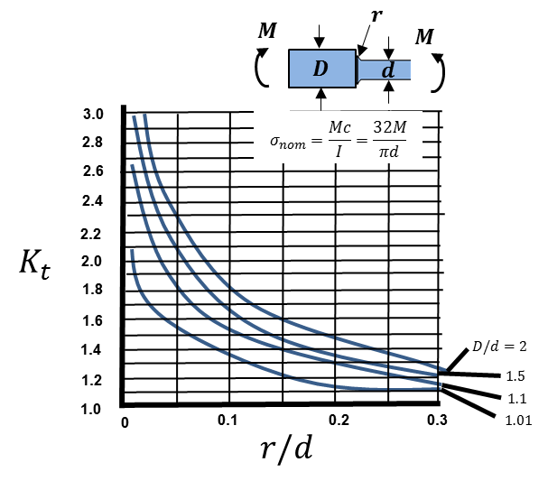
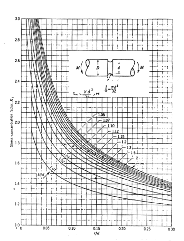
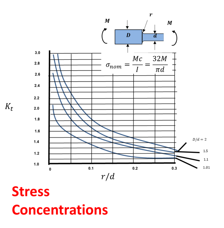
Stress Concentration Factor Chart - This page provides a set of interactive plots for common stress. During the design phase, there are multiple approaches to estimating stress concentration factors. The factor kt depends mainly on the geometry of the notch, not on the material, except when the material deforms severely under load. Σ0 = mc/i, where c = d/2, i = td3/12, and t is the thickness. Σ0 = f/a, where a = πd2/4. Note the red regions having higher stress values. Kt values are normally obtained from plots such as in figure 2 and arestrictly valid only for ideally elastic, stiff members. T s = yy = 3 s o figure 3.6: Web figure 1 stress distribution (simplistic) in a notched member under uniaxial load. Σ0 = f/a, where a = dt and t is the thickness. K ts d/d 0 0.05 0.10 0.15 0.20 0.25 0.30 2.4 2.8 3.2 3.6 4.0 j c t b d t d3 16 dd2 6. Σ0 = f/a, where a = πd2/4. Τ0 = tc/j, where c = d/2 and j = πd4/32. During the design phase, there are multiple approaches to estimating stress concentration factors. Σ0 = mc/i, where. During the design phase, there are multiple approaches to estimating stress concentration factors. Σ0 = mc/i, where c = d/2, i = td3/12, and t is the thickness. Kt values are normally obtained from plots such as in figure 2 and arestrictly valid only for ideally elastic, stiff members. Web figure 1 stress distribution (simplistic) in a notched member under. Web figure 1 stress distribution (simplistic) in a notched member under uniaxial load. Web in this tutorial, we will examine the standard method of accounting for stress concentrations caused by geometric features. This page provides a set of interactive plots for common stress. Σ0 = f/a, where a = πd2/4. Web the stress concentration factor for a circular hole in. Web the stress concentration factor for a circular hole in an infinite plate: The factor kt depends mainly on the geometry of the notch, not on the material, except when the material deforms severely under load. During the design phase, there are multiple approaches to estimating stress concentration factors. Web there are experimental methods for measuring stress concentration factors including. K ts d/d 0 0.05 0.10 0.15 0.20 0.25 0.30 2.4 2.8 3.2 3.6 4.0 j c t b d t d3 16 dd2 6. Web in this tutorial, we will examine the standard method of accounting for stress concentrations caused by geometric features. This page provides a set of interactive plots for common stress. Σ0 = f/a, where a. Web figure 1 stress distribution (simplistic) in a notched member under uniaxial load. Σ0 = mc/i, where c = d/2, i = td3/12, and t is the thickness. T s = yy = 3 s o figure 3.6: The factor kt depends mainly on the geometry of the notch, not on the material, except when the material deforms severely under. Kt values are normally obtained from plots such as in figure 2 and arestrictly valid only for ideally elastic, stiff members. Web figure 1 stress distribution (simplistic) in a notched member under uniaxial load. Σ0 = mc/i, where c = d/2, i = td3/12, and t is the thickness. The factor kt depends mainly on the geometry of the notch,. Kt values are normally obtained from plots such as in figure 2 and arestrictly valid only for ideally elastic, stiff members. Web figure 1 stress distribution (simplistic) in a notched member under uniaxial load. Τ0 = tc/j, where c = d/2 and j = πd4/32. During the design phase, there are multiple approaches to estimating stress concentration factors. Web the. Web figure 1 stress distribution (simplistic) in a notched member under uniaxial load. Τ0 = tc/j, where c = d/2 and j = πd4/32. Σ0 = f/a, where a = πd2/4. This page provides a set of interactive plots for common stress. The factor kt depends mainly on the geometry of the notch, not on the material, except when the. The factor kt depends mainly on the geometry of the notch, not on the material, except when the material deforms severely under load. Web in this tutorial, we will examine the standard method of accounting for stress concentrations caused by geometric features. K ts d/d 0 0.05 0.10 0.15 0.20 0.25 0.30 2.4 2.8 3.2 3.6 4.0 j c t. This page provides a set of interactive plots for common stress. Σ0 = f/a, where a = dt and t is the thickness. During the design phase, there are multiple approaches to estimating stress concentration factors. Note the red regions having higher stress values. Σ0 = mc/i, where c = d/2, i = td3/12, and t is the thickness. K ts d/d 0 0.05 0.10 0.15 0.20 0.25 0.30 2.4 2.8 3.2 3.6 4.0 j c t b d t d3 16 dd2 6. T s = yy = 3 s o figure 3.6: Web the stress concentration factor for a circular hole in an infinite plate: Web there are experimental methods for measuring stress concentration factors including photoelastic stress analysis, thermoelastic stress analysis, brittle coatings or strain gauges. Τ0 = tc/j, where c = d/2 and j = πd4/32. Web figure 1 stress distribution (simplistic) in a notched member under uniaxial load. Kt values are normally obtained from plots such as in figure 2 and arestrictly valid only for ideally elastic, stiff members.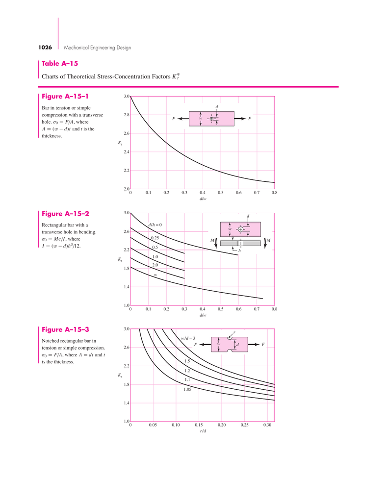
Table A15 Charts of Theoretical Stress
Stress Concentration Factors A Fundamental Example Top Dog Engineer
Solved In This Section You Will Compute The Fatigue Life

Stress CONCENTRATION Factors and Factor of Safety in 11 Minutes! YouTube

Stress concentration factor for a shaft with a shoulder fillet in axial

Stress Concentration Factor Chart A Visual Reference of Charts Chart
Stress Concentration Factors A Fundamental Example Top Dog Engineer
Solved Charts of Theoretical StressConcentration Factors
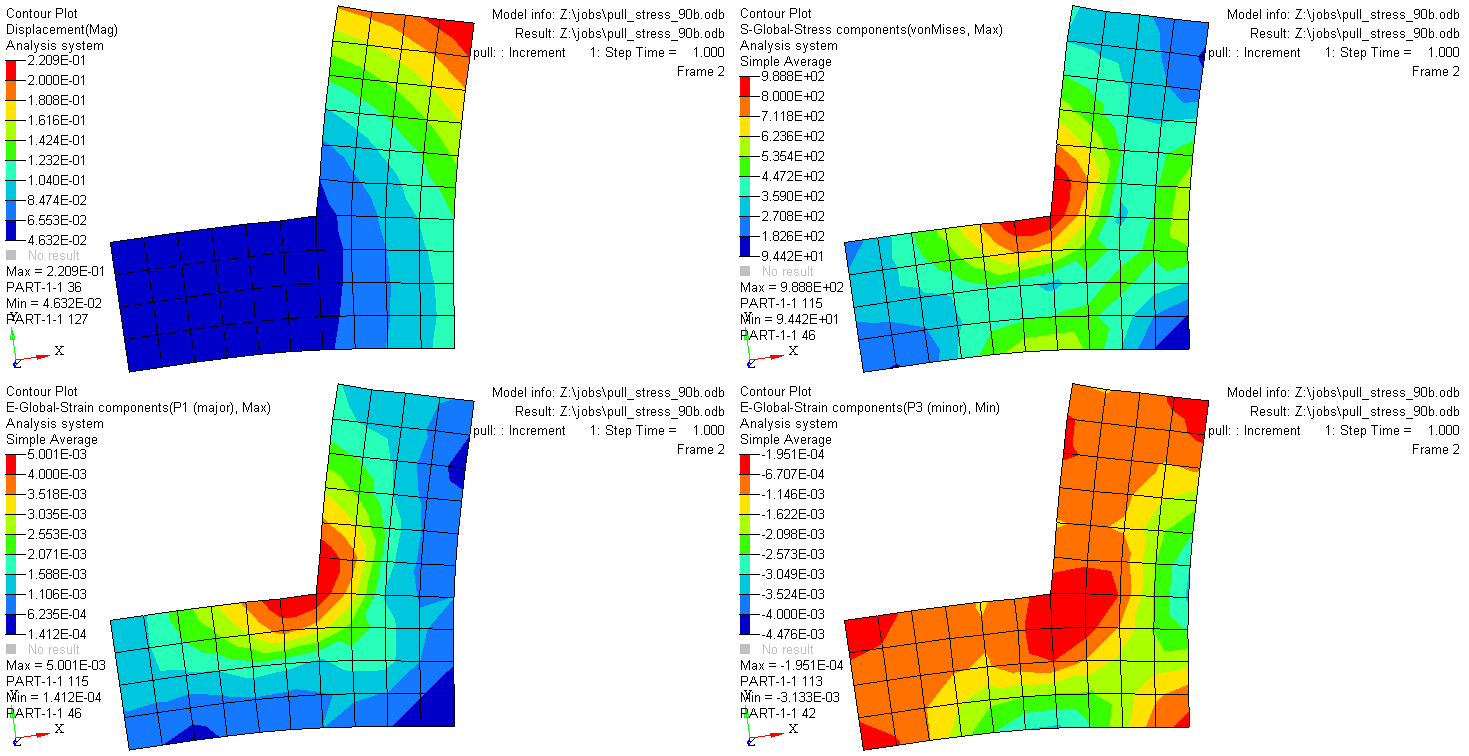
Learning to DO Understanding Stress Concentrations Using Finite

PPT Stress and Strain Axial Loading PowerPoint Presentation ID569156
Stress Distribution In Plates With Cutouts;
The Factor Kt Depends Mainly On The Geometry Of The Notch, Not On The Material, Except When The Material Deforms Severely Under Load.
Σ0 = F/A, Where A = Πd2/4.
Web In This Tutorial, We Will Examine The Standard Method Of Accounting For Stress Concentrations Caused By Geometric Features.
Related Post: