Tolerance Charting
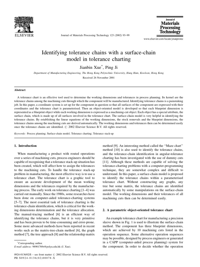
Tolerance Charting - Direct limits, or as tolerance values applied directly to a dimension. The tolerance chart is a tolerance analysis tool used by process planners in the determination of the working dimensions and tolerances of components during their manufacture. Web a tolerance chart is an effective tool used to determine the working dimensions and tolerances in process planning. Geometric tolerances, indicated by special symbols related to part surfaces. Enter your desired preferred tolerance grade and the nomial size. This paper presents an efficient method of automatically determining the working dimensions and their balanced tolerances. The following engineering calculator will show the plus and minus tolerance for the specific iso 286 hole tolerance data. A method for tolerance charting is presented based on a graph. The control of tolerances is important in. Web this web page contains links to mechanical tolerance design manufacturing calculators and tables, gd&t, geometric dimensioning and tolerancing calculators, standard mechanical tolerances and other mechanical tolerance resources for design, engineering, manufacturing and quality. This paper presents an efficient method of automatically determining the working dimensions and their balanced tolerances. Web the first provides the charts for the fundamental deviations (g, j, etc.) and tolerance grades (7, 8, 9, etc.), out of which the limits of the tolerance classes (h7, g6, etc.) can be calculated. You can check the tolerance chart below: Find your. The control of tolerances is important in. Web the tolerance charting method enables the calculation of working tolerances in machining process planning. Tolerance charting is an effective tool to determine the optimal allocation of working dimensions and working tolerances such that the blueprint dimensions and tolerances can be achieved to accomplish the cost objectives. Web a tolerance chart is an. Web this paper presents an efficient method of integrating the process of allocating optimum b/p tolerances in product design with the process of tolerance charting in process planning. Web a measured value or physical property of a material, manufactured object, system, or service; Notes referring to specific conditions, usually placed next to the corresponding dimensions. This method ensures that the. Other measured values (such as temperature, humidity, etc.); The type of fit is clearance. Enter your desired preferred tolerance grade and the nomial size. Web owing to the impractical solution from the linear programming (lp) model, a proportional smoothing approach is described with a numerical example, which can assign appropriate tolerances automatically and systematically, based on the requirements of both. The method has been used as a basic tool for analysing process plans for many decades. Web a tolerance chart is an effective tool used to determine the working dimensions and tolerances in process planning. Web a measured value or physical property of a material, manufactured object, system, or service; Web the first provides the charts for the fundamental deviations. The international journal of advanced manufacturing technology aims and scope submit manuscript. Other measured values (such as temperature, humidity, etc.); Web tolerance diagram 6 h7 g6. Web a tolerance chart is a necessary part of planning of manufacturing processes and a graphical representation of the process plan. In engineering and safety, a physical distance or space (tolerance), as in a. Geometric tolerances, indicated by special symbols related to part surfaces. Process capability in tolerance charting is modelled using the tolerances of the working dimensions. Identifying tolerance chains is a painstaking job. Web a tolerance chart is an effective tool used to determine the working dimensions and tolerances in process planning. Direct limits, or as tolerance values applied directly to a. The complete system, comprising the tolerance charting and optimization modules, is finally tested on an example. The following engineering calculator will show the plus and minus tolerance for the specific iso 286 hole tolerance data. Web table of metric hole tolerances per. Find your data faster with our fits and tolerance calculator. Web the first provides the charts for the. Web this web page contains links to mechanical tolerance design manufacturing calculators and tables, gd&t, geometric dimensioning and tolerancing calculators, standard mechanical tolerances and other mechanical tolerance resources for design, engineering, manufacturing and quality. Web a tolerance chart is a necessary part of planning of manufacturing processes and a graphical representation of the process plan. Web table of metric hole. This method ensures that the assembly is manufactured with optimum working dimensions and tolerances and yet satisfies all the assembly requirements. Web the tolerance balancing process is accomplished using a separate mathematical model. Its kernel are the tolerance chains among the machining cuts through which the component will be manufactured. Geometric tolerances, indicated by special symbols related to part surfaces.. The method has been used as a basic tool for analysing process plans for many decades. The international journal of advanced manufacturing technology aims and scope submit manuscript. Find your data faster with our fits and tolerance calculator. Direct limits, or as tolerance values applied directly to a dimension. A method for tolerance charting is presented based on a graph. The control of tolerances is important in. Green = prefered tolerance classes. The type of fit is clearance. Click on to get additional tolerance options. Web tolerance diagram 6 h7 g6. Web a tolerance chart is a necessary part of planning of manufacturing processes and a graphical representation of the process plan. Identifying tolerance chains is a painstaking job. Geometric tolerances, indicated by special symbols related to part surfaces. Its kernel are the tolerance chains among the machining cuts through which the component will be manufactured. Web a measured value or physical property of a material, manufactured object, system, or service; Web the first provides the charts for the fundamental deviations (g, j, etc.) and tolerance grades (7, 8, 9, etc.), out of which the limits of the tolerance classes (h7, g6, etc.) can be calculated.Tolerance Charting

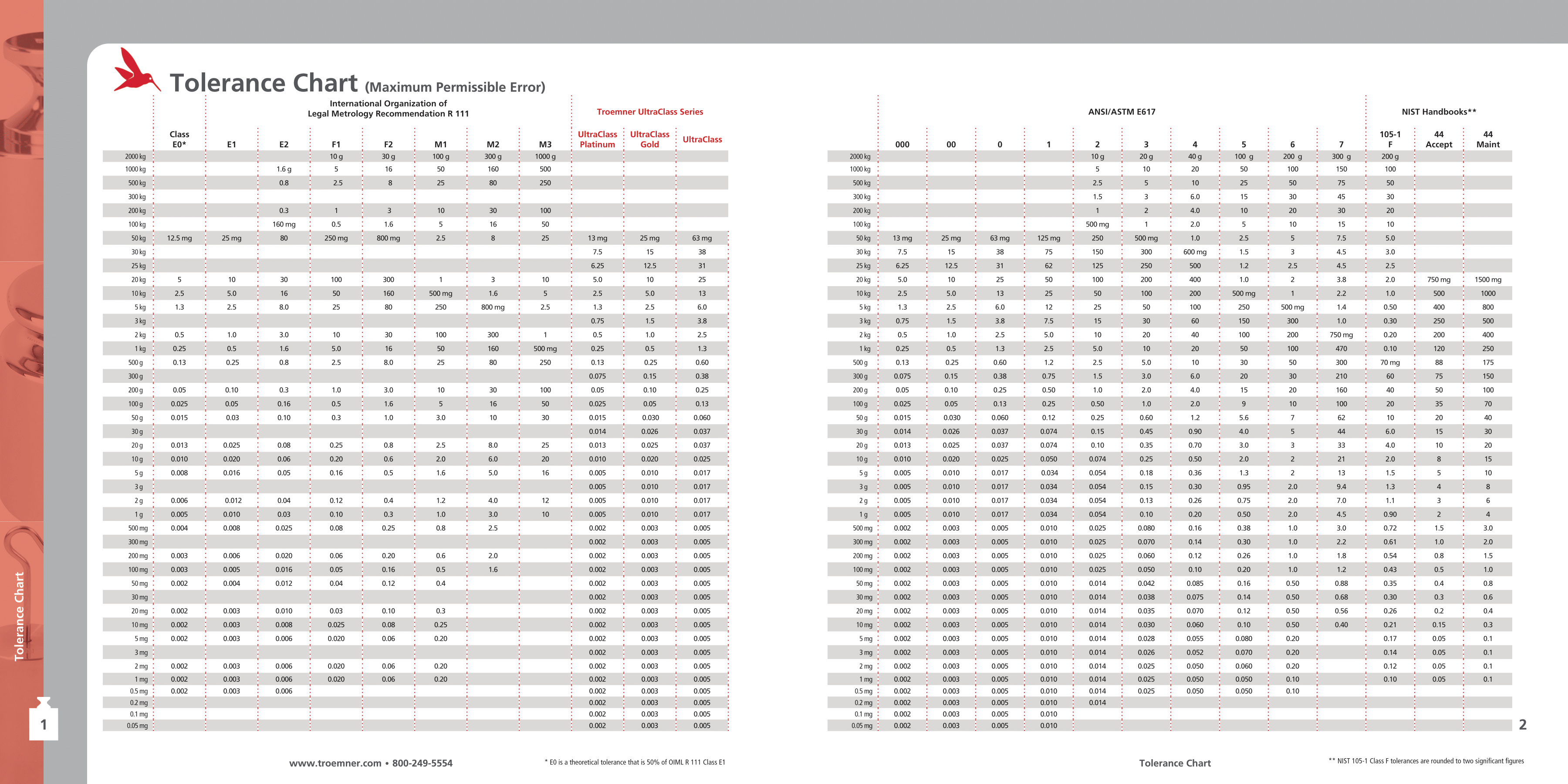
Tolerance chart
MRM Metrology Inc.
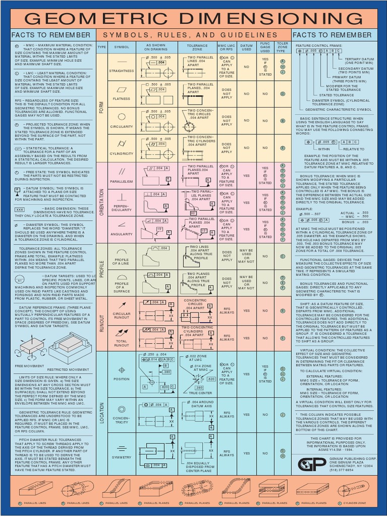
Geometric Tolerance Chart Engineering Tolerance Geometry

Tolerance charting 8 YouTube

How to Determine Bearing Shaft and Housing Fit Baart Group

Tolerance charting 11 YouTube

Tolerance charting 4 YouTube

Tolerance Free of Charge Creative Commons Handwriting image

Fragment of the tolerance chart form valid for turning of a cylindrical
This Paper Presents An Efficient Method Of Automatically Determining The Working Dimensions And Their Balanced Tolerances.
In Engineering And Safety, A Physical Distance Or Space (Tolerance), As In A Truck (Lorry), Train Or Boat Under A Bridge As Well As A Train In A Tunnel (See Structure Gauge And Loading Gauge );
The Complete System, Comprising The Tolerance Charting And Optimization Modules, Is Finally Tested On An Example.
Web This Web Page Contains Links To Mechanical Tolerance Design Manufacturing Calculators And Tables, Gd&T, Geometric Dimensioning And Tolerancing Calculators, Standard Mechanical Tolerances And Other Mechanical Tolerance Resources For Design, Engineering, Manufacturing And Quality.
Related Post: