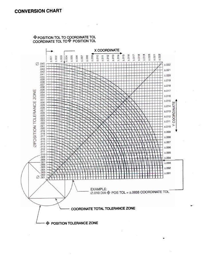
True Position Chart
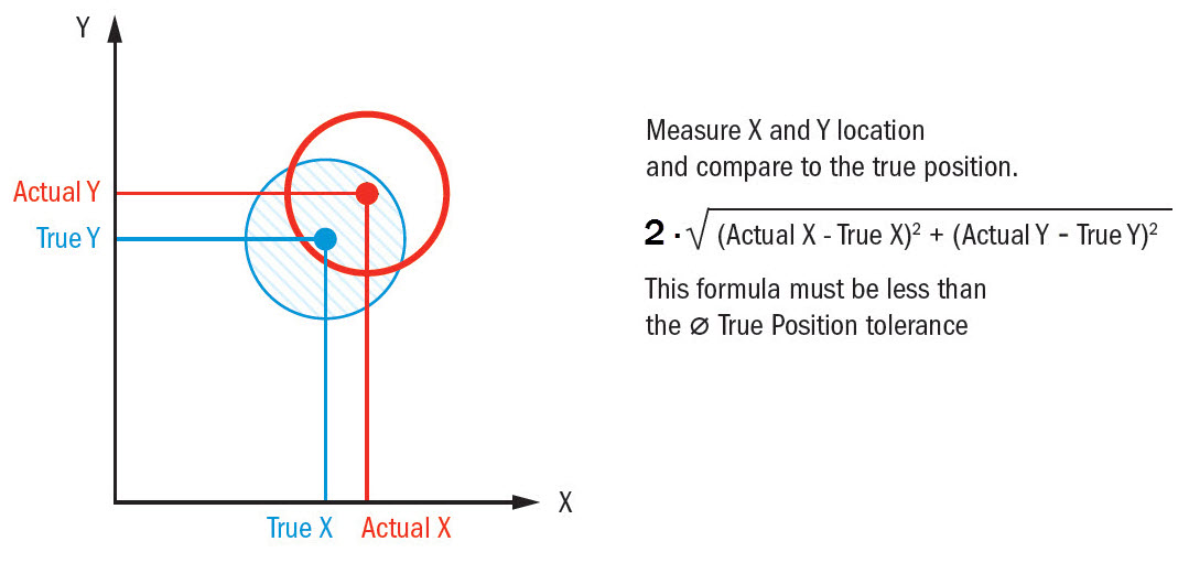
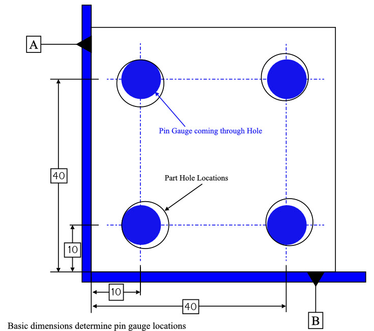
True Position Chart - Convert your x and y deviation measurements into an actual diametric deviation, which you can then compare to the position tolerance listed in your feature control frame. Red → the actual position is outside the permitted range. True position formula (without mmc/lmc) p = 2 ∗ ( a 0 − a 1) 2 + ( b 0 − b 1) 2. We use this concept in gd&t to control the variation of a specific feature from its desired position. Web calculate your true position with gd&t basics’ handy calculator. Distance in x and y from a datum. 3d/gd&t inspection by anyone, anywhere. Web true position gd&t tolerance calculator. This is important for mating parts to ensure a seamless assembly. Tolerances, engineering design & limits & fits resources. It is more correctly referred to as “position”. In other words, the geometric dimensioning and tolerancing “position” tolerance is how far your feature’s location can vary from its “true position”. Distance in x and y from a datum. Negative tolerance numbers indicate out of tolerance condition. Tolerances, engineering design & limits & fits resources. Depending on how it is called out, true position can be used in a lot of different ways. Web the “ true position” is the exact coordinate, or location defined by basic dimensions or other means that represents the nominal value. Convert your x and y deviation measurements into an actual diametric deviation, which you can then compare to the. Negative tolerance numbers indicate out of tolerance condition. A pass/fail judgment is performed using a measuring gauge or inspection gauge. Let's make that simpler with an example. True position formula (without mmc/lmc) p = 2 ∗ ( a 0 − a 1) 2 + ( b 0 − b 1) 2. Usually, you specify the exact point where your position. True position is a gd&t symbol that defines the permissible variation of a feature’s location from its “ideal” position. Web the “ true position” is the exact coordinate, or location defined by basic dimensions or other means that represents the nominal value. Typically a hole, shaft, slot, or keyway. 3d/gd&t inspection by anyone, anywhere. Web true position gd&t tolerance calculator. It is more correctly referred to as “position”. Tolerances, engineering design & limits & fits resources. Convert your x and y deviation measurements into an actual diametric deviation, which you can then compare to the position tolerance listed in your feature control frame. Depending on how it is called out, true position can be used in a lot of different. 3d/gd&t inspection by anyone, anywhere. Web calculate your true position with gd&t basics’ handy calculator. Negative tolerance numbers indicate out of tolerance condition. We use this concept in gd&t to control the variation of a specific feature from its desired position. Web true position gd&t tolerance calculator. Convert your x and y deviation measurements into an actual diametric deviation, which you can then compare to the position tolerance listed in your feature control frame. Holes are the most popular feature where true position is used with. A pass/fail judgment is performed using a measuring gauge or inspection gauge. Web true position can be 2 or 3 dimensional. 3d/gd&t inspection by anyone, anywhere. Web consideration of the bonus tolerance. In other words, the geometric dimensioning and tolerancing “position” tolerance is how far your feature’s location can vary from its “true position”. Convert your x and y deviation measurements into an actual diametric deviation, which you can then compare to the position tolerance listed in your feature control frame.. True position is a gd&t symbol that defines the permissible variation of a feature’s location from its “ideal” position. Typically a hole, shaft, slot, or keyway. A pass/fail judgment is performed using a measuring gauge or inspection gauge. It is more correctly referred to as “position”. Convert your x and y deviation measurements into an actual diametric deviation, which you. Web the easiest way to measure true position. Red → the actual position is outside the permitted range. Web true position can be 2 or 3 dimensional (and will need an appropriate number of corresponding datums). 3d/gd&t inspection by anyone, anywhere. True position formula (without mmc/lmc) p = 2 ∗ ( a 0 − a 1) 2 + ( b. Web the “ true position” is the exact coordinate, or location defined by basic dimensions or other means that represents the nominal value. Web calculate your true position with gd&t basics’ handy calculator. Web true position is a gd&t callout for specifying the position of a feature. Let's make that simpler with an example. 3d/gd&t inspection by anyone, anywhere. True position is a gd&t symbol that defines the permissible variation of a feature’s location from its “ideal” position. Convert your x and y deviation measurements into an actual diametric deviation, which you can then compare to the position tolerance listed in your feature control frame. This is important for mating parts to ensure a seamless assembly. Tolerances, engineering design & limits & fits resources. Usually, you specify the exact point where your position should be and use true position to tell how far away from that position is acceptible. In other words, the geometric dimensioning and tolerancing “position” tolerance is how far your feature’s location can vary from its “true position”. Holes are the most popular feature where true position is used with. Red → the actual position is outside the permitted range. Depending on how it is called out, true position can be used in a lot of different ways. Distance in x and y from a datum. Green → the actual position is within the allowed tolerance.
True Position GD&T Basics
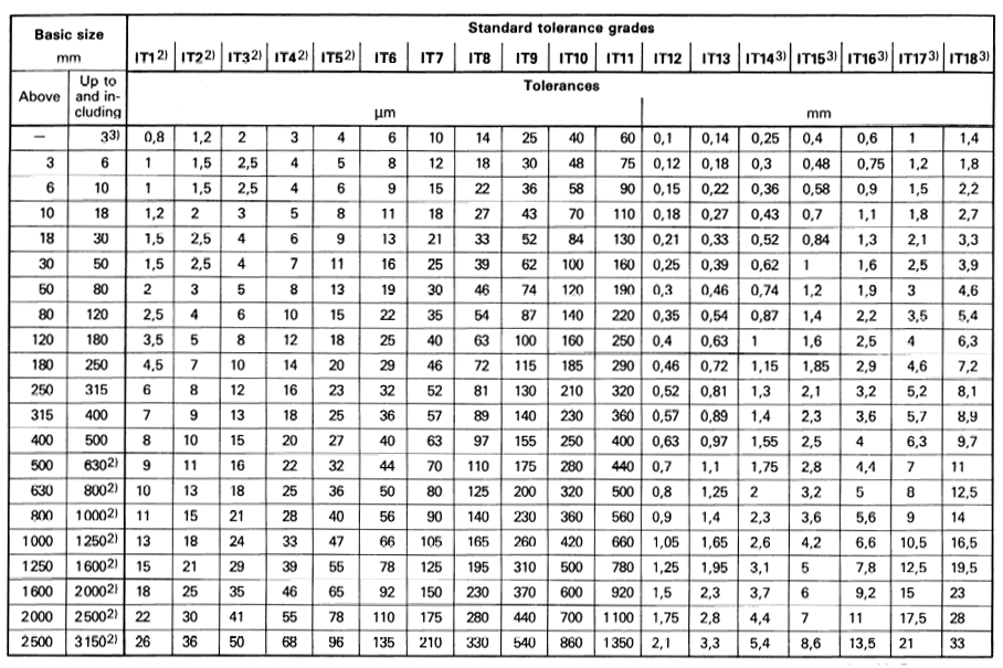
International Tolerance (IT) Grades Table Chart Engineers Edge
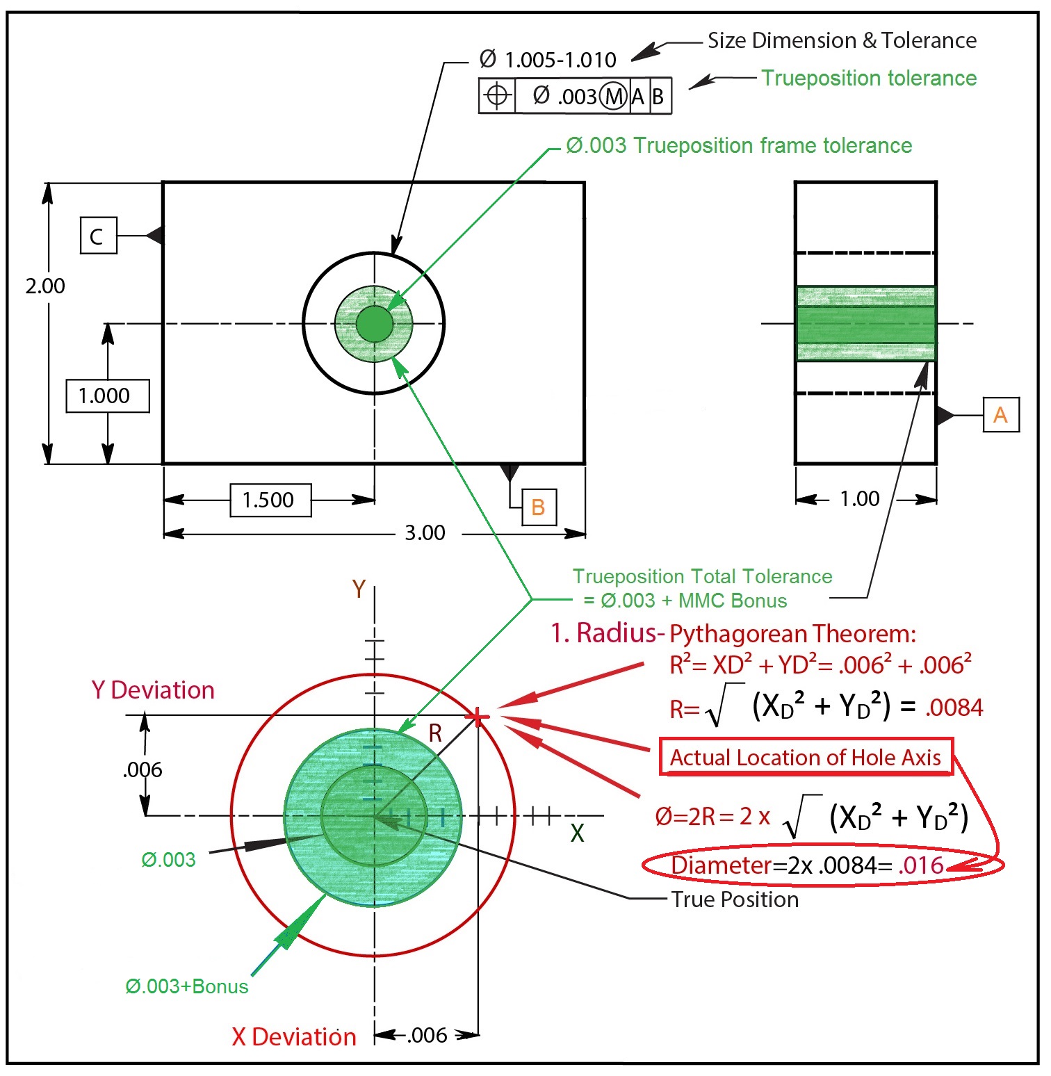
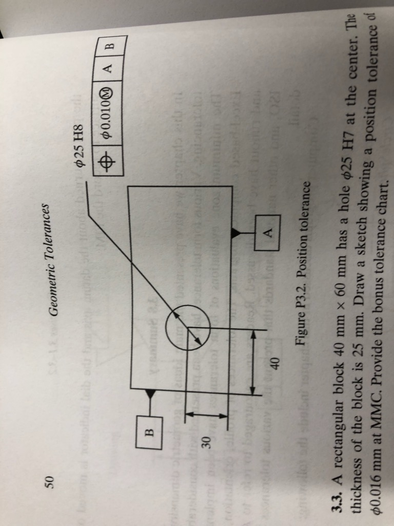
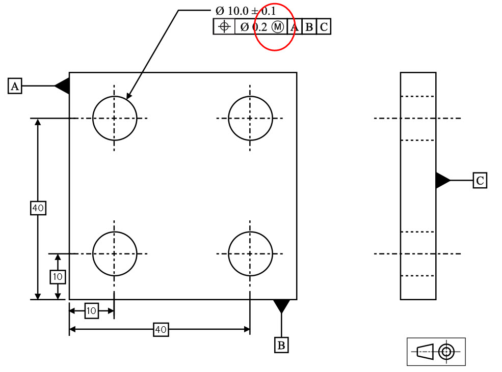
Total positional tolerance at material condition
True Position GD&T Basics
True Position GD&T Basics

The Beginner's Guide to GD&T True Position + Free Calculator
True Position Wall Chart
Solved 3.2. Calculate the allowable true position values for
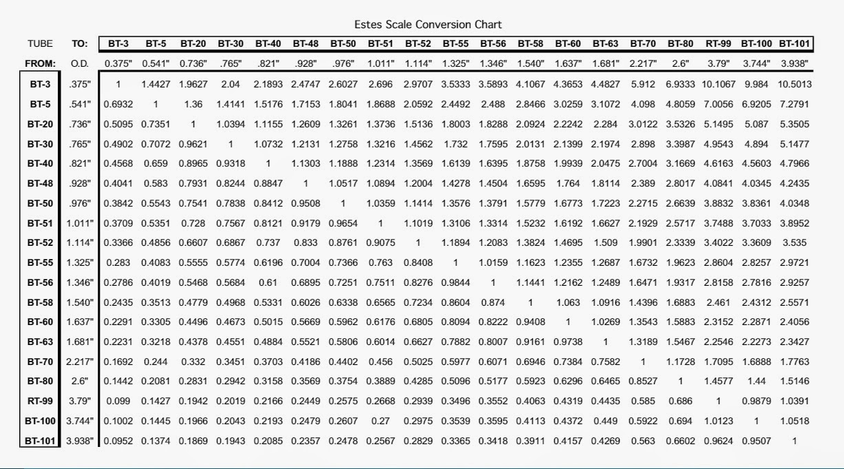
Model Rocket Building Lonnie B's Conversion Chart
True Position GD&T Basics
It Is More Correctly Referred To As “Position”.
Negative Tolerance Numbers Indicate Out Of Tolerance Condition.
True Position Formula (Without Mmc/Lmc) P = 2 ∗ ( A 0 − A 1) 2 + ( B 0 − B 1) 2.
We Use This Concept In Gd&T To Control The Variation Of A Specific Feature From Its Desired Position.
Related Post: